Abstract- The accepted models of the origin of interference in body surface potential recordings predict that it would be advantageous to perform signal amplification on the electrode. A suitable circuit for a miniature biopotential amplifier to be manufactured in thick-film technology is described. A prototype series of active electrodes was produced and tested. The high immunity to interference resulted in ECG and EEG recordings of a very high quality.
The usual transducers in biopotential measurements (electrodes) are passive metal discs
with a connecting wire to the electronic circuitry. This setup has the advantage of
mechanical simplicity. However, from an engineering point of view it is unattractive to
have a significant length of connection wire between a high impedance signal source (the
electrode) and the measurement circuitry. Instead, the ideal solution would be to perform
signal amplification as close to the transducers as possible. There are indeed a number of
practical problems with the current passive electrodes. Unshielded electrode wires are
usually the major source of power supply line (50 Hz) interference; the mechanism has been
described in a previous paper [1]. A solution can be formed by using shielded electrode
wires and although good suppression of power supply line interference can be achieved with
this method, widespread clinical use is hampered by the costs and by the delicacy of the
low-noise shielded wires and the coaxial connectors.
Another problem with the passive electrodes in modern biopotential measurement systems
originates from the current trend to combine low-noise analog circuitry and fast logic in
the front-end. It was argued in an earlier paper that optimal instrumentation in terms of
interference rejection and patient-safety should consist of a small battery powered
front-end with a fiber-optic connection to the signal-processing hard-ware (usually a PC)
[2]. With currently available components, the best solution is to perform the analog to
digital conver-sion in the isolated front-end and to use a digital transmission format for
the fiber-optic transmission link. A consequence of such a setup is, however, that special
attention has to be paid to the problem of interference from the digital circuitry coupled
into the sensitive analog input circuitry.
The two described problems could in principle be solved if the analog signal processing
would be performed at the electrode. Such an active transducer would form a signal source
with a low output impedance which would eliminate the need for shielded wires. In
addition, proper shielding of the digital circuitry with respect to the analog input
amplifiers would be feasible.
Other instrumentation groups have developed active electrodes in the past. The
electronics of these transducers always consisted of a buffer amplifier. Although this
setup solves the problem of cable interference and can be designed to need only a two lead
connection wire [3], there remains an important disadvantages. Because the signal is not
amplified there is still needed an extensive low-noise amplifier stage in the front-end
with its described problems with respect to HF interference. Therefore, we chose a
different approach by attempting to perform all analog signal processing, e.g.
amplification and DC rejection, at the electrode and to retain the usual configuration of
amplifying the biopotential signal with respect to a reference signal [4].
The main design goals were to keep the size and costs of the electrode comparable to a
standard EEG electrode. The cost factor eliminated the possibility of a custom made
integrated circuit. We found a good alternative in combining thick-film technology with an
amplifier design developed by our group to be used with a minimal number of parts [4]; the
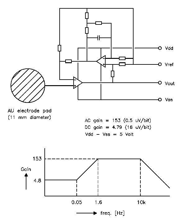
circuitdiagram is shown in Fig. 1
.
Fig. 1 The circuit diagram and transfer function of the active electrode. The stopped integrator in the feedback loop reduces the gain for low frequencies in order to keep the relatively large electrode offset voltages within the dynamic range of a 16 bit ADC.
 |
|
Active electrode, first experimental
version
|
The electronic components are mounted at one side of a ceramic substrate with a diameter of 11 mm, while the other side is covered with a printed gold layer to form the electrode surface. The electronics are sealed with epoxy. The electrode is equipped with a 4 lead ribbon wire of 1 meter length with a small low-cost crimp connector. No expensive components or production processes have been used.
The active electrodes were tested in combination with a fiber coupled 32-channel front-end. The front-end consisted of a 16-bit ADC for each channel, an optical fiber transmission circuit, timing logic and a NiMH battery pack, housed in a compact box positioned close to the subject. The system was interfaced to a standard PC by a commercially available digital I/O card. In order to test the new setup, EEG and ECG signals were recorded with the electrodes applied to the unprepared skin with a typical electrode paste (Elefix, Nihon Kohden Corporation). The measurements were performed in a typical laboratory room full of electrical equipment. All measurements showed an exceptionally low noise level and a complete absence of 50 Hz interference. One of the EEG measurements is shown in Fig. 2. Note that the shown signals are raw data, no data processing other than bandwidth limiting has been performed.
Although the signal quality of the active electrodes is satisfactory, there are some
practical problems to be solved before the electrodes can be regarded to be an alternative
for the commonly used passive electrodes. The cost of this new technology will be a
decisive factor determining the general acceptance of this new type of electrodes.
Production costs were kept minimal by using only well established thick-film production
techniques and by designing the electronics around easily available standard components (1
dual opamp in naked chip version, 8 SMD metal-film resistors and 1 SMD capacitor). The
projected production costs for large series is in the order of US$ 10. Some practical
details need further improving. The current used ribbon cable is cheap and easily mounted
with a connector but not really flexible enough for day-to-day clinical use. Another point
of further research is the combination of the chosen electrode material and the various
electrode pastes which at the moment is the limiting factor for the signal quality.
It was shown that a high signal quality can be achieved with the developed active electrodes on the unprepared skin. We expect that using this method of concentrating the analog circuitry on the electrode will be the most economical way of producing high-quality biopotential recording systems.
This work was supported by the Technology Foundation STW. under grant No. AGN44.3416.
[1] A. C. MettingVanRijn, A. Peper and C. A. Grimbergen, "High-quality recording of bioelectric events. I: interference reduction, theory and practice," Med. & Biol. Eng. & Comput., vol. 28, pp. 389-397, 1990.
[2] A. C. MettingVanRijn, A. P. Kuiper, A. C. Linnenbank and C. A. Grimbergen, "Patient isolation in multichannel bioelectric recordings by digital transmission through a single optical fiber," IEEE Trans. Biomed. Eng., vol. 40, pp. 302-308, 1993.
[3] F. Z. Padmadinata, J. J. Veerhoek, G. J. A. Van Dijk and J. H. Huijsing, "Microelectronic skin electrode," Sensors and Actuators, vol. B1, pp. 491-494, 1990.
[4] A. C. MettingVanRijn, A. Peper and C. A. Grimbergen, "Amplifiers for bioelectric events: a design with a minimal number of parts". Med. & Biol. Eng. & Comput., vol. 32, pp. 305-310, 1994. Fig. 2 An EEG signal measured with the active electrodes on the unprepared skin. Note the low noise level of approx 3 ćVpk-pk and the absence of 50 Hz interference.