|
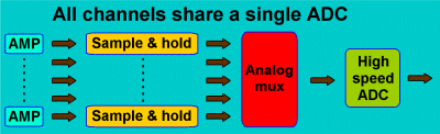
Until approx. 10 years ago, high performance analog-to-digital converters
were relatively expensive components with a high power consumption. This
prohibited using more than one ADC for a system. There were problems with
the Shared-ADC-setup though. The need for sampling all the channels at
exactly the same moment forced designers to include sample-an-hold circuits.
Together with the limitations imposed by the analog multiplexer, many
problems surfaced in the Shared-ADC-setup.
| Problems
arising with the Shared-ADC-setup: |
| 1) |
The
dynamic range of the S/H and analog multiplexer circuitry is limited
to approx. 80 dB (14 bit). This means that relatively high amplifier
gain is needed to lift the input noise above the noise level of the
S/H and MUX. High amplifier gain decreases the input range, and thus
eliminates the possibility of DC amplifiers. |
| 2) |
Charge
leakage currents in the S/H circuits causes gain differences between
all channels. |
| 3) |
Charge
injection by the switching of the analog multiplexer imposes glitches
on the S/H output. |
| 4) |
The
analog multiplexer has limited channel separation. Besides measurement
errors, this has the nasty effect of high crosstalk to neighboring
channels when one of the electrodes isn't properly connected. Not
nice when you are measuring many channels. |
| 5) |
The
output of the analog MUX is a staircase like signal, with the sequential
S/H voltages. This means that for every next channel, the ADC has
to quickly settle on a new signal level. This imposes extreme demands
on the bandwidth, frequency response and settling time of the analog
input stage of the ADC (and on intermediate buffer amplifier stages
which may be needed from preventing loading the MUX output). Effects
like overshoot and ringing lead to further deterioration of the sampling
precision. |
| 6) |
On
systems with many channels (say 128 and more), proper routing of all
the sensitive analog signals to the single analog MUX becomes a formidable
task (interference problems become huge) |
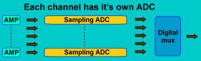
During
the early nineties, researchers kept asking for systems with higher dynamic
range (to allow DC measurements), better channel separation, and more
channels than could practically be achieved with the Shared-ADC-setup.
Advancing developments in low-power, high-bit ADCs and low-power Programmable
Logic Devices (PLD) allowed designers of modern multichannel acquisition
systems to switch to the ADC-per-channel setup. BioSemi already introduced
the new setup on the Mark-6 system in 1995, and has since then continued
to improve the setup in terms of miniaturization, power consumption and
reduced costs. The ADCs operate synchronously, so no sampling skew is
present (all ADCs perform the conversion at the same moment). The multiplexing
operation is now performed entirely digital, so any deterioration of the
signal is eliminated. The dynamic range of the system can now be really
equal to the dynamic range of the ADC. The 24
bit ActiveTwo with its 110 dB dynamic range and >110 dB channel
separation is a good example of the advantages which can be achieved by
using one ADC-per-channel. Specs like these are fully unattainable with
the older setup (30-40 dB worse, a factor of nearly 100).
The
important step forward that could be achieved by using an ADC-per-channel
and digital multiplexing, forced all serious manufacturers to use this
setup for their new designs. Consequently, you will only find the Shared-ADC-setup
in older designs.
Customers
not acquainted with the performance features of modern ADCs, sometimes
raise the question whether the new setup does not introduce additional
errors as a result of differences between the ADCs. As they see it, the
use of a Shared-ADC-setup at least ensures hat any ADC error is the same
for all channels, and thus cancels when the difference between channels
is displayed. Although this assumption is not untrue, these customers
ignore that the differences between modern ADCs in a properly designed
circuit topology are much smaller than the errors introduced by the analog
multiplexing circuitry.
A
lot of work has gone into optimizing the circuitry used in our systems
in order to minimize channel differences. One of the key design features
is that we use a Zero reference setup
with a common Reference voltage for all (up to 256) ADCs. The circuit
board has been optimized (regardless of costs) for identical REF voltage
for all ADCs. For example: REF is distributed among the ADCs by low-impedance,
low inductance ground planes, a method effectively preventing small voltage
drops across the motherboard. Consequently, this is one of the reasons
why we insist on having all modules on one single motherboard. You can
never attain this kind of precision when you start coupling subsections
with for example 32 channels. Another feature of the "Zero reference
setup" is that we make a final subtraction of the channels in software,
effectively canceling all noise and drift effects of the ADC references.
Finally, all the ADCs run on the same master clock to prevent any timing
differences between the ADCs (which may effect the conversion).
In
a multichannel system, there are always small gain differences between
the channels. Part of these differences are caused by resistor tolerances
in the amplifier stage between active electrode and ADC, and the other
part is caused by tolerances in the analog sections of the ADCs. The difference
between the ADCs is much less than 1% (guaranteed by the manufacturer,
and checked by us). We found that the dominating source of gain errors
between the channels are resistor tolerances in the amplifiers. BioSemi
exclusively uses precision metal film resistors to ensure high accuracy
and stability over time. We specify an overall gain accuracy of 1% (both
absolute and relative). Further software calibration can be added for
anyone insisting on better accuracy. It should be noted that the amplifier
gain tolerance problem is exactly the same when using a Shared-ADC-setup
scanning the channels.
Given
the excellent accuracy of modern ADCs, and the way they can be made to
perform identical in a properly designed system, the ADC-per-channel setup
actually makes it far more easier to ensure equality of the channels than
the obsolete Shared-ADC-setup |


