|
| Is it possible to adjust the amplifier gain on BioSemi systems ? |
| |
| No, the amplifier gain is fixed on our systems. It is true that many competing systems use impressive looking hardware switches to allow the user to select different gain settings. However, the dynamic range of our systems is large enough to acquire all biopotential signals with a single fixed gain setting. This setup makes the hardware simple and reliable, and minimizes component count, size, costs and power consumption. |
| |
The ActiveTwo has an analog input (potential differences, voltages), and a digital output (24 bit words). The gain (scaling) between input and output is 31.25 nV/bit (1/32th uV). The gain can be calculated by dividing the analog input range (+262,144 mV to -262,144 mV) by the digital output range (+2^23 to -2^23). The "exact gain of the amplifier of the Biosemi ActiveTwo" is an internal design parameter that is not relevant to the user because an analog output signal is not available, see here. BioSemi does not provide information about the specific design of the electronics. |
| |
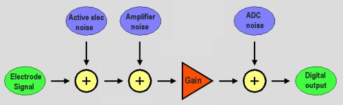
| In a digital biopotential measurement system like the ActiveTwo, there is a chain of three basic noise sources: the input buffer in the active electrode, the amplifier with gain in the AD-box, and the analog-to-digital converter (ADC). In a properly designed biopotential system, the noise of the input stage (the active electrode in case of a BioSemi system) is the dominating noise source of the complete chain, while this input noise itself should be well below the noise level of the electrode-skin interface. The function of amplifier gain is to lift the noise of the input stage above the noise floors of the following stages (Motchenbacher and Fitchen, 1972). |
| |
|
| |
| The low noise level of the input stage is nowadays a question of choosing the right opamp. Although there is ample choice in low-noise opamp's, many of them - especially bipolar audio types - are less suitable for bioamp applications because of high input bias currents, limited input impedance, and/or high susceptibility for high frequency interference. BioSemi uses a CMOS input type which has proven to be a good compromise between the various demands. |
| |
| The next stage is the post amplifier. Because the gain in the active electrode is 1, the noise level of the post amplifier is equally important. In case of the ActiveTwo, the input noise level of the post amplifier is lower than the noise of the active electrodes, so the last ones are the dominating noise source. |
| |
| The last noise source in the signal chain is the ADC. Because the ADC converts the analog signal to discrete steps, quantization noise is added to the signal. With a Successive Approximation Register (SAR) type ADC like we used in the ActiveOne and older systems, the noise level of the ADC is simply dependent on the LSB magnitude: quantization noise has a RMS voltage of LSB/Ö12 (Linnenbank et al., 1995). With a Delta-Sigma (DS) type converter like we use in our latest ActiveTwo system, the situation is more complicated. In a DS converter, a conversion result is calculated from many 1 bit conversions, and the noise level is generally much higher than the LSB value. However, with modern DS converters, the dynamic range (the ration between max. signal and noise level) still exceed the best SAR types. For example: the 24 bit DS ADC used in our new ActiveTwo system has a dynamic range of approx. 110 dB. this means that it has 19 effective bits, and that the 5 Least significant bits are noise. While this might be a disappointment for someone who assumed that the ADC would actually be able to sample the signal in 2^24 discrete steps, the performance is still impressive. The 24-bit ADC it's dynamic range is a factor of 8 larger than the best 16 bit SAR types. |
| |
| At this point the designer has to make the following tradeoff: on the one hand we want a high amplifier gain to lift the amplifier input noise far above the ADC noise level (thus minimizing contribution of the ADC noise), on the other hand, we want a low amplifier gain to achieve a large amplifier input range (the amplifier should not saturate on electrode offset voltages and artifacts). The setting chosen on the ActiveTwo is quite optimal: the input range of +262mV to -262 mV is ample for all electrode offsets, while the ADC noise is still less than half of the amplifier noise (the squares of the noise magnitudes added, the ADC contributes 12% to the total noise). Reducing the ADC noise by increasing the gain further would have only a very small effect on the total noise level, whereas the headroom for electrode offsets would decrease proportionally with the increased gain. For example: a factor of 10 larger gain would reduce the total noise only by a mere 10%, while the new +/- 26mV input range would make DC measurement very awkward due to saturation on electrode offsets. |
| |
| The small range of sensible gain settings present, and the minor differences in noise which are found within this range of gains, does not merit the extra complication of variable gain. |
| |
| |
| Still not convinced ? , then consider the following example: |
| |
Turning up the volume helps you to hear the telephone call better when you are in a noisy bar, but it does NOT improve anything when the line itself is bad. (the dominating noise source is BEFORE amplification, as with the ActiveTwo) |
|
| |
| |
| References : |
| Linnenbank, A. C., MettingVanRijn, A. C., Grimbergen, C. A., and DeBakker, J. M. T. (1995) Choosing the resolution in AD conversion of biomedical signals. Proc. of the XXIInd International Congress on Electro cardiology, Nijmegen, The Netherlands, 16, 198-199. |
| Motchenbacher, C.D. and Fitchen, F.C. (1972) Low noise electronic design. John Wiley & Sons, New York, 185-187. |
| |
|